| 62IN SERIES | INDEX |
| BACK | NEXT | |
|
Key / Keyway orientations
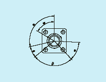
Angles shown are with reference to the major key or keyway. In receptacles, the major keyway always remains fixed in relation to the mounting flange. For B, C, E and F orientations, the three bayonet locations and associated minor keywaysare rotated completely as shown in the tables. Theaccompanying diagram shows a receptacle shell with keyways. Corresponding key orientations for a mating plug shell are therefore always clockwise.
|
||||||||||||||||||||||||||||||||||||||||||||||||||||||||||||||||||||||||||||||||||||||||||||||||||||||||||||||||||||||||||||||||||||||||||||||||||||||||||||||||||||||||||||||||||||||||||||||||||||||||||||||||||||||||||||||||||||||||||||||||||||||||||||||||||||||||||||||||||||||||||||||||||||||||||||||||||||||||||||||||
| BACK | NEXT | ||||||||||||||||||||||||||||||||||||||||||||||||||||||||||||||||||||||||||||||||||||||||||||||||||||||||||||||||||||||||||||||||||||||||||||||||||||||||||||||||||||||||||||||||||||||||||||||||||||||||||||||||||||||||||||||||||||||||||||||||||||||||||||||||||||||||||||||||||||||||||||||||||||||||||||||||||||||||||||||||
